United We Stand

Brainerd Area Amateur Radio Club  

Club Meeting March 28, 2002

    The Brainerd Area Amateur Radio Club met on Thursday, March 28th at 7 PM for a monthly business meeting.  

Draft Repeater Report:
The response to the survey in the BAARCer was minimal, only seven responses.  These comments along with conversations with various members yielded the following:

Perceived problems with current repeater system
Adjacent channel interference to 030 from 015  
Lack of courtesy beep on 030
Physical access to 440 (courthouse)
Noise problems (autopatch related) on 030

Current system utilization
030 medium daytime, light at night, heavier on weekends
130 virtually no activity except for Sunday night net
440 virtually no activity except for Sunday night net

Desirements
Slave receiver sites
Superlink
Link to Wadena
Packet

Funding
Less than $1000

Labor
Lots needed
The most significant system problem is the adjacent channel interference to 030.  This could be by either swapping the 030 and 130 systems, or by obtaining a new frequency allocation from the MN coordinator.  Swapping of the two repeaters is the simpler.  A new allocation would require recrystalling and retuning of the current 030 hardware.

  The value of three repeaters given the current utilization is highly questionable.  The 130 and 440 repeaters are basically space heaters.  The coverage of either system  is less than the 030 system.

  The addition of slave receivers to the system would provide better coverage in selected locations.  Slave receivers and link transmitters are a relatively inexpensive way to provide extended coverage.

  The addition of SuperLink access is potentially good.  This would require additional equipment, perhaps using the existing current 440 and 030 hardware assets.

  Linking to the Wadena repeater is conceptually good but the Wadena club is essentially broke!!  Just throw some money their way!!   Long time in the future planning.

  There is some interest in considering packet as part of the system upgrade.  Packet is probably better served by a standalone system not colocated with any repeater systems.  Interference is highly probable.

  The general consensus is that no more than $1000 be spent on upgrades or changes to the current system.  This will require use of current assets in so far as possible and used equipment from other sources as well as donations.  It will be a challenge to meet such a budget.  A phased approach, one step at a time, is necessary. 

  Any changes should be made so that future growth can be made without reworking the system each time.  We cannot rebuild the system each time we want to make a change. 

  A good deal of labor will be required to make changes.  The effort must be closely coordinated to ensure that the system is not disabled or any significant length of time.  Whoever manages the effort should be given all the support possible.  Of particular importance is that we not have several “bosses” working in conflicting direction.

Recommendations:
1.  Swap the current 030 and 130 systems, maintaining the Autopatch at the current site.  The 130 machine will become the primary for all activities.  The 030 will continue to operate from the old 130 site. 
2.  Monitor the activity of the relocated 030 to determine if its operation should be terminated.
3.  Investigate method to employ the current 440 as part of a link to SuperLink.  Additional hardware may be necessary.  If the relocated 030 hardware could be used in conjunction with the 440 unit to provide SuperLink capability, it should be so used.
4.  The current 440 Duplexer is property of W0WUG.  The club should purchase the unit from him if the 440 system is retained.  If not retained or required, it should be returned to him.

  It is important that any changes be approved by the club membership.  Any additional comments an recommendations to be included in the final report should be made no later than the next club meeting.  Submitted by John Oehlenschlager KØJO.

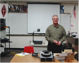
    At 8:15 PM, Roger Williams WØWUG explained oscillator crystals, how they are manufactured, and how they are used.  This was a good informative presentation by someone who knows the subject well. 


The presenter, Roger Williams, WØWUG, wishes to thank everyone for their hospitality, and kind comments after the club meeting.   Due to the constraints of the time and that  I had too much material, I would like to offer a few helpful tips ,and some clarification.   Here are some quartz crystal do’s and don’ts for radio tech’s and experimenters.

  Do:

  • Apply well filtered DC supply voltage to  oscillator circuits.
  • Apply well regulated DC supply voltage. Oscillator frequency will vary with poor supply voltage conditions, and/or be modulated with “hum” or noise.
  • Try to prevent extreme shock(dropping) to equipment. Modern radio equipment is tough, but a hard fall  has been known to fracture crystals.
  • Try to isolate radio equipment from mechanical vibration. It’s possible that road vibration in a vehicle can mechanically modulate the oscillator, which will impart that noise to the transmitted or received signal.

Don’t:

  • Cut the header wire leads or pins with a diagonal cutter. The mechanical shock can fracture the crystal inside the holder. A hemostat device should be clamped on the lead near the holder  to absorb the  shock of cutting .
  • Solder on the pins of a crystal holder without heat-sinking. Heat will travel up the header leads inside the housing, and can fracture the crystal.
  • Solder on the outside of the crystal can, especially if it has a soldered-over “exhaust-hole”. If the hole opens up, humidity and air contaminants will ruin the crystal.
  • Pull a metal can,or glass encased crystal out of a socket with a pliers! The case may be crushed or broken.If you must use a long-nose pliers, be careful!
  • Adjust crystal frequency “trimmer capacitors” unless the radio unit has had about one hour to stabilize to room temperature.

At the beginning of the program Thursday, I mentioned  we were going to discuss alternating current, physics, and music. Well, we got to two of the three subtopics in the allotted time.

It is a fact in science (physics) that wave motion, and wave generation follows the same rules and principles whether the waves are on a lake, sound waves produced by a vibrating string (guitar, piano,violin) , or high frequency alternating current waves produced by an oscillator circuit employing a quartz crystal.

The music reference was in regard to the phenomenon of  a vibrating mass like a stringed instrument, a vibrating reed in a wind instrument, or quartz crystal. Physical characteristics of these  devices  produce varying levels of multiple output signals contained in the harmonics and overtones of the output sound or wave.

What this means is that different instruments playing the exact same note sound uniquely different. A  trumpet sounds different than a violin,etc, due to the signal strength of the harmonics and overtones emitted. Another way of saying this is that what you hear is not just a single tone but a result of many tones at different levels.

 The same is true with quartz crystals, but we use selectivity (filtering) to pick out the one signal required by the circuit design, otherwise we would be transmitting (or receiving) on several frequencies at once!.

Definitions of harmonics and overtones can be found on the last page of the article reprint handed out at the club meeting so we won’t repeat it here.

The point we are getting to is that some high frequency quartz crystals   above 30 MHz for example, would be impossible to manufacture because of the extremely thin wafer theoretically required.

So crystal makers  are able to manipulate the crystal shape and curvature such that it physically has the dimensions of a lower frequency (fundamental)crystal, but “likes” to operate at a much higher harmonic frequency. This technique can produce oscillations to about 200MHz. In practical terms, crystals operate best in the 5MHz to 20MHz frequencies.

Some overtone “orders” can be troublesome however. Due to the phase relationship ( signal voltage polarities) of all the harmonics (whole number multiples) being produced at once during oscillation, some of these combine in ways that are  displeasing to the ear, or relating to quartz crystals, some overtone “orders” can be troublesome and unstable.  

I’ve tried to simplify a lot of “heady” stuff here to aid  peoples understanding  that a simple looking device , a quartz wafer in a sealed container is a very complicated and precision electronic component.

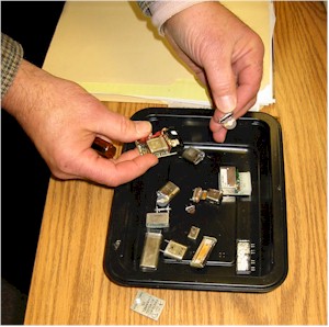
     Just some of many oscillator crystals and crystal oscillators shown to the group.

     A fun time was had by all.

Back to the BAARC History Page        Back to 2002

Back to the BAARC Main Page

This page was last updated 12/19/2006  Ø