
 |
| United We Stand |
|
|
|
|
|
Brainerd Area Amateur Radio Club |
|
Club Membership Meeting on Thursday, July 26, 2007 |
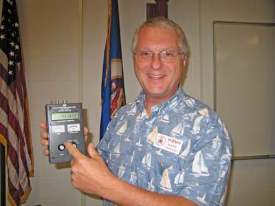
| The July Membership Meeting was held at the Brainerd Main Fire Station. After the business meeting and coffee break, those assembled learned about antenna analyzers and VSWR from Mark WØMH. |
|
When I was a 16-year-old Novice Ham, one of my first transmitters was a one-tube CW rig. The trick was to put the key down and then tune as quickly as possible for minimum glow on the tube. Was I tuning for low VSWR into a 50-ohm load? No, I was tuning the transmitter output section to match the antenna impedance. One antenna was dipole at about 70 Ohms and the other was a long wire with a very unknown impedance. Regardless, this tuning procedure got the rig on the air. What is different today? Well, our solid-state rigs are designed and built to a 50-ohm standard. We could use a 75 ohm line impedance as the television receiver industry does. I think they settled on 75 ohms because a standard 300 ohm balanced-feed antenna can be easily be transformed to 75 ohms unbalanced using a simple 4:1 balun transformer. There was a 51.5 ohm standard at one time too along with a few others. Though a process of elimination, 50 ohms has become the standard for two-way radio, radio broadcast, television broadcast, and most of Ham radio. There is nothing “magic” about 50 ohms except it is the “standard” to which most of our equipment is built. Ohms Law tells us that with 1000 watts into 50 ohms, we will have 4.47 Amperes of current flow and 224 volts RMS. By the way, Ohms is often abbreviated by the Greek symbol Omega. Impedance matching and transferring power is more than just having an antenna with a 50-ohm feed-point resistance. The equation almost always includes a transmission line (coaxial cable). If you have a 50-ohm antenna and a 75 Ohm transmission line, then your rig will probably not see 50 ohms. In this case, the length of the line will determine the impedance the rig sees. To keep it simple, you should use a 50-ohm line on a 50-ohm antenna. Many rigs are fix-tuned and need to see a 50-ohm load. If the rig does not see 50 ohms, then it will not deliver the expected power to the antenna. The final power amplifier could overheat and fail or go into VSWR fold-back. This is a common problem on HF mobile rigs. Conversely, your receiver will not have all the apparent sensitivity it could have if the input is not 50 ohms. Try this for yourself someday: On HF, adjust your antenna tuner for low VSWR on transmit. Listen to a weak signal on or near that frequency. Then misadjust the tuner. The signal will fade down . Yes, that’s right, you need a good impedance match to effectively couple power from the antenna to the receiver. What are we doing with an antenna tuner? Well, we are adjusting the transmission line and antenna combination to 50-ohms impedance so the rig is happy. The tuner is a “variable transformer” What is VSWR? It is Voltage Standing Wave Ratio, sometimes known as SWR (Standing Wave Ratio). The strict definition is, “The ratio of the maximum voltage to the minimum voltage resulting from the interaction of the forward and reflected waves.” How do we get reflected waves? It is the lack of proper impedance matching. A good example is an open or a shorted transmission line where the RF power gets to the end of the line and has no way of being consumed so it is reflected much like light is reflected in a mirror. When transmitting, we want the RF power to be completely absorbed/consumed by the antenna. The antenna in turn radiates the signal in the air. Any RF energy that is not radiated is lost as heat, much as in a dummy load. Yes, a dummy load will have low VSWR if it is 50 ohms too. A dummy load, as you know, will convert virtually all of the input RF directly to heat. Just a little RF will leak out into the air. A really great tool for testing and adjusting antennas and antenna systems is an antenna analyzer. Because all antennas are frequency selective, the antenna analyzer needs to operate at just one frequency at a time giving antenna impedance data on the frequency of interest. How does an antenna analyzer do its work? Well, it transmits a very low level signal and uses a “bridge” circuit to determine what impedance it sees. I use one as a part of my HF Ham station. Rather than putting 100 or 400 watts on the air to adjust my antenna tuner, I use the antenna analyzer to adjust the antenna tuner. Because the power is a low 20 milliwatts (.002 watts), almost no one will know I am tuning-up. It also avoids me being called a “lid.” This procedure also reduces stress on my rig and linear amplifier. A simple RF switch allows my rig to work into the antenna or the antenna analyzer. Editor's note: Mark demonstrated an MFJ-259 Anatenna Analyzer for the assembled group. There is a VSWR chart on the Ham Tips section of this website. Editor’s note: Mark Persons, WØMH, is Certified by the Society of Broadcast Engineers as a Professional Broadcast Engineer with over 30 years experience. |
|
 |
Paula WØHA and Terry KIØFW. |
 |
Darrell ABØVP and Steve KCØYTE. |
 |
Fritz WØKO and Roger WØWUG. |
| The next Membership Meeting is our Annual Fox Hunt and Picnic on August 18th. Everyone is welcome and encouraged to attend. |
|
Comments?
|
This page was last updated 09/08/2007 Ø